


What Is the OSI Model? A Complete Layer-by-Layer Guide for Beginners and Professionals
Discover the OSI Model — the 7-layer framework that defines how data travels across a network. This complete guide by Croszeduverse (Amos Peter Blogs) breaks down each layer with real-world examples, making it easy for beginners and professionals to understand networking fundamentals.
Introduction: Why Does the OSI Model Matter?
Have you ever wondered how a message you send on WhatsApp travels from your phone, through the internet, and appears almost instantly on your friend's screen thousands of miles away? Or how a video call manages to sync voice and video in real time across continents?
The answer lies in a foundational concept in computer networking the OSI Model.
The Open Systems Interconnection (OSI) Model is a conceptual framework developed to standardize how different computer systems communicate over a network. Think of it as the universal rulebook that every device follows when sending and receiving data regardless of the hardware manufacturer or software vendor.
Whether you are a student stepping into the world of IT, a developer building networked applications, or an IT professional troubleshooting a slow connection, understanding the OSI model is not optional it is essential.
In this guide, Croszeduverse (Amos Peter Blogs) breaks down the OSI model from scratch: what it is, why it was created, how each of the 7 layers works, and how they all connect to make the internet function.
What Is the OSI Model?
The OSI (Open Systems Interconnection) Model is a 7-layer conceptual framework created by the International Organization for Standardization (ISO) in 1984. Its primary purpose was to provide a universal standard for how different networking systems — from IBM mainframes to Unix servers to personal computers could communicate with one another, regardless of their underlying architecture.
Before the OSI model, networking was a fragmented mess. Each vendor had its own proprietary communication protocol, which meant that an IBM machine and a Digital Equipment Corporation (DEC) machine could not easily talk to each other. The OSI model solved this by dividing network communication into seven distinct, manageable layers, each with a specific role.
Key Insight: The OSI model is not a protocol itself. It is a model — a reference guide that describes how protocols should work and interact.
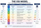
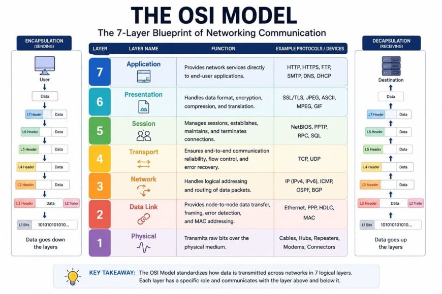
The 7 Layers of the OSI Model — Quick Reference
| Layer | Number | Name | Key Role |
|---|---|---|---|
| Layer 7 | Application | Application Layer | User-facing interfaces and services |
| Layer 6 | Presentation | Presentation Layer | Data formatting, encryption, compression |
| Layer 5 | Session | Session Layer | Managing communication sessions |
| Layer 4 | Transport | Transport Layer | Reliable data delivery (TCP/UDP) |
| Layer 3 | Network | Network Layer | Routing and IP addressing |
| Layer 2 | Data Link | Data Link Layer | Node-to-node data transfer, MAC addressing |
| Layer 1 | Physical | Physical Layer | Raw bits over physical media |
Memory Tip — All People Seem To Need Data Processing (Application → Presentation → Session → Transport → Network → Data Link → Physical)
Layer 1 — The Physical Layer
What it does: The Physical Layer is the lowest and most fundamental layer of the OSI model. It is responsible for the transmission of raw, unstructured binary data (bits — 0s and 1s) over a physical medium such as copper cables, fiber optic cables, or radio waves (in the case of Wi-Fi).
This layer defines the physical and electrical characteristics of the hardware:
- Voltage levels (what constitutes a binary 1 or 0)
- Cable types (Cat5, Cat6, fiber optic, coaxial)
- Connector types (RJ45, USB, HDMI)
- Data transmission rate (bandwidth in bits per second)
- Transmission mode (simplex, half-duplex, full-duplex)
Real-World Analogy: Think of the Physical Layer as the road on which data travels. Just like a road does not care about what is being transported — cars, trucks, motorcycles — the Physical Layer simply moves bits without understanding what they mean.
Real-World Example: When you plug an Ethernet cable into your laptop, the cable, network card, and the electrical signals passing through are all part of the Physical Layer.
Devices at this layer: Hubs, repeaters, network cables, modems, fiber optic transmitters.
Common Protocols/Standards: Ethernet (IEEE 802.3), USB, Bluetooth (physical aspects), DSL.
Layer 2 — The Data Link Layer
What it does: The Data Link Layer is responsible for node-to-node data transfer — that is, transferring data between two devices that are directly connected (on the same network segment). It takes raw bits from the Physical Layer and packages them into frames.
This layer has two sub-layers:
- MAC (Media Access Control): Controls how devices access the physical network medium and uses MAC addresses (hardware addresses burned into network interface cards) to identify devices on the local network.
- LLC (Logical Link Control): Handles error checking and flow control between devices.
Key Responsibilities:
- Physical addressing (MAC addresses)
- Error detection and correction (but not correction at all protocols)
- Frame synchronization
- Flow control between adjacent nodes
Real-World Analogy: If the Physical Layer is the road, the Data Link Layer is the traffic officer at an intersection — making sure data gets from one device to the immediately next device correctly, without collisions.
Real-World Example: When your laptop sends data to your Wi-Fi router, the Data Link Layer handles the MAC address-based communication between these two devices.
Devices at this layer: Switches, bridges, network interface cards (NICs).
Common Protocols: Ethernet, Wi-Fi (IEEE 802.11), PPP (Point-to-Point Protocol), ARP (Address Resolution Protocol).
Layer 3 — The Network Layer
What it does: The Network Layer is responsible for routing data packets across multiple networks to reach their final destination. While the Data Link Layer handles communication between directly connected devices, the Network Layer handles end-to-end delivery across an entire network — including the internet.
Key Responsibilities:
- Logical addressing using IP addresses (IPv4 and IPv6)
- Routing — determining the best path for data to travel from source to destination
- Packet fragmentation and reassembly — breaking large data into smaller packets if needed
- Traffic control and congestion management
Real-World Analogy: Think of the Network Layer as a GPS navigation system. Just as GPS calculates the best route from your starting point to your destination (accounting for roads, traffic, and detours), the Network Layer determines the most efficient path for your data packet to travel across the internet.
Real-World Example: When you type www.croszeduverse.com into your browser, the Network Layer determines the IP address of the web server and figures out the best route for your data request to travel from your device, through multiple routers, across the internet, to reach that server.
Devices at this layer: Routers, Layer 3 switches.
Common Protocols: IP (IPv4, IPv6), ICMP (used by the ping command), OSPF, BGP, RIP.
Layer 4 — The Transport Layer
What it does: The Transport Layer is the backbone of reliable communication. It ensures that data is delivered completely, in the correct order, and without errors — from the source application on one device to the destination application on another.
Key Responsibilities:
- Segmentation — breaking data into smaller segments for transmission
- Flow control — ensuring the sender doesn't overwhelm the receiver
- Error control — detecting and requesting retransmission of lost or corrupted segments
- Port addressing — identifying which specific application or service the data is destined for (e.g., port 80 for HTTP, port 443 for HTTPS)
The Two Major Protocols at this Layer:
| Feature | TCP (Transmission Control Protocol) | UDP (User Datagram Protocol) |
|---|---|---|
| Connection type | Connection-oriented | Connectionless |
| Reliability | Highly reliable — guarantees delivery | Unreliable — no delivery guarantee |
| Speed | Slower (acknowledgment required) | Faster (fire-and-forget) |
| Use cases | Web browsing, email, file transfer | Video streaming, online gaming, DNS |
Real-World Analogy: The Transport Layer is like a postal service with tracking. TCP is like certified mail — you get confirmation of delivery. UDP is like dropping a flyer in someone's mailbox — faster, but no guarantee they'll pick it up.
Real-World Example: When you load a webpage (HTTP/HTTPS), TCP at the Transport Layer ensures every piece of the page is delivered correctly. When you stream a YouTube video, UDP is used — a few dropped frames are acceptable, but low latency is critical.
Layer 5 — The Session Layer
What it does: The Session Layer is responsible for establishing, maintaining, and terminating communication sessions between two applications. A session is essentially an ongoing, managed conversation between two networked devices.
Key Responsibilities:
- Session establishment — setting up the communication connection
- Session maintenance — keeping the session alive during communication
- Session termination — gracefully closing the session when done
- Synchronization — using checkpoints so that interrupted sessions can resume from a known point rather than starting over
- Dialog control — managing whether communication is simplex, half-duplex, or full-duplex
Real-World Analogy: The Session Layer is like a phone call. Someone initiates the call (session establishment), the conversation takes place (session maintenance), and when done, both parties say "goodbye" and hang up (session termination). If the call drops in the middle of a conversation, you can call back and continue from where you left off.
Real-World Example: When you log into your online banking portal, the Session Layer manages your authenticated session — ensuring your connection is maintained while you navigate, and properly terminated when you log out.
Common Protocols: NetBIOS, RPC (Remote Procedure Call), PPTP, SQL sessions.
Layer 6 — The Presentation Layer
What it does: The Presentation Layer acts as a translator and data formatter between the application layer and the rest of the network. It is responsible for ensuring that data sent from one application can be read by the application on the receiving end — regardless of differences in format, encoding, or operating system.
Key Responsibilities:
- Data translation/conversion — converting data between different formats (e.g., EBCDIC to ASCII)
- Data encryption and decryption — protecting data during transmission (SSL/TLS encryption operates here)
- Data compression and decompression — reducing data size for efficient transmission
Real-World Analogy: The Presentation Layer is like a universal translator. Imagine two people speaking different languages — the translator converts the message so both parties understand each other perfectly. Similarly, the Presentation Layer ensures that data sent in one format is received and understood in another.
Real-World Example: When you access a website using HTTPS, the Presentation Layer handles the SSL/TLS encryption that scrambles your data before transmission and decrypts it on arrival keeping your passwords and credit card numbers safe.
Common Formats and Protocols: SSL/TLS, JPEG, PNG, GIF, MPEG, ASCII, EBCDIC, JSON, XML.
Layer 7 — The Application Layer
What it does: The Application Layer is the topmost layer of the OSI model and the one closest to the end user. It provides network services directly to user-facing applications — it is where the human interaction with the network begins.
Contrary to what the name might suggest, the Application Layer does not refer to software applications like Chrome or Microsoft Word. Rather, it provides the protocols and services that these applications use to communicate over the network.
Key Responsibilities:
- Providing network services to applications (email, file transfer, web browsing)
- Identifying communication partners and their availability
- Synchronizing communication between applications
- Managing resource availability
Common Protocols at this Layer:
| Protocol | Purpose |
|---|---|
| HTTP / HTTPS | Web browsing |
| SMTP / IMAP / POP3 | Email communication |
| FTP / SFTP | File transfer |
| DNS | Domain name resolution |
| DHCP | IP address assignment |
| SNMP | Network management |
| Telnet / SSH | Remote access |
Real-World Analogy: The Application Layer is the front desk of a hotel. It is the face of the entire operation — the point where guests (users) interact and make requests, which are then handled by all the other layers working behind the scenes.
Real-World Example: Every time you open Google Chrome and type a URL, your browser uses HTTP/HTTPS (Application Layer protocols) to request a webpage. Everything else — encryption, routing, physical transmission — happens in the layers below, invisibly and automatically.
How the Layers Work Together: Data Encapsulation
One of the most important concepts in the OSI model is data encapsulation — the process by which data is wrapped with headers (and sometimes trailers) as it moves down the layers on the sending device, and unwrapped as it moves up the layers on the receiving device.
Sending Side (Encapsulation — Top to Bottom):
- Application Layer → Creates data (e.g., an HTTP request)
- Presentation Layer → Formats, compresses, encrypts the data
- Session Layer → Adds session information
- Transport Layer → Breaks data into segments, adds port numbers
- Network Layer → Wraps segments into packets, adds IP addresses
- Data Link Layer → Wraps packets into frames, adds MAC addresses
- Physical Layer → Converts frames into bits and transmits over the medium
Receiving Side (Decapsulation — Bottom to Top): The process reverses — each layer strips off its corresponding header/trailer and passes the data upward until the original message reaches the application.
Think of it this way: Sending data through the OSI layers is like putting a letter in an envelope (Application), addressing it (Network), sealing and stamping it (Transport/Data Link), and putting it in a mailbox (Physical). Receiving is the reverse — opening each wrapper to get to the letter inside.
OSI Model vs. TCP/IP Model
The OSI Model is often compared to the TCP/IP Model, which is the practical model actually used on the internet today.
| OSI Model Layer | TCP/IP Model Equivalent |
|---|---|
| Application (Layer 7) | Application |
| Presentation (Layer 6) | Application |
| Session (Layer 5) | Application |
| Transport (Layer 4) | Transport |
| Network (Layer 3) | Internet |
| Data Link (Layer 2) | Network Access |
| Physical (Layer 1) | Network Access |
Key Differences:
- The OSI model has 7 layers; TCP/IP has 4 layers
- OSI is a theoretical reference model; TCP/IP is a practical, implemented model
- The OSI model separates Presentation and Session as distinct layers; TCP/IP collapses them into the Application layer
- TCP/IP was developed before the OSI model but gained widespread adoption; OSI is used primarily as a teaching and troubleshooting framework
Why the OSI Model Still Matters Today
You might ask: "If TCP/IP is what the internet actually uses, why should I learn the OSI model?"
Here is why:
- Universal Troubleshooting Framework — IT professionals and network engineers use OSI layers to systematically diagnose network problems. "Is the issue at Layer 1 (physical cable)? Layer 3 (routing)? Layer 7 (application)?"
- Vendor-Neutral Communication — The OSI model gives engineers a common language to describe networking concepts regardless of brand or technology.
- Foundation for Certifications — The OSI model is a core topic in major IT certifications including CompTIA Network+, CCNA (Cisco), CEH, and CISSP.
- Security Analysis — Cybersecurity professionals use OSI layers to identify at which layer an attack is occurring and design targeted defenses.
- Protocol Development — Developers and protocol designers use OSI as a reference when creating new communication standards.
Common OSI Model Interview Questions
- What are the 7 layers of the OSI model? — Physical, Data Link, Network, Transport, Session, Presentation, Application.
- What is the difference between Layer 2 and Layer 3 switches? — Layer 2 switches use MAC addresses (Data Link); Layer 3 switches also perform routing using IP addresses (Network Layer).
- At which layer does encryption occur? — Primarily at Layer 6 (Presentation), though encryption can also be implemented at other layers.
- What is the PDU (Protocol Data Unit) at each layer? — Bits (Layer 1), Frames (Layer 2), Packets (Layer 3), Segments (Layer 4), Data (Layers 5–7).
- Which layer is responsible for end-to-end delivery? — The Transport Layer (Layer 4).
Summary
The OSI model is the cornerstone of modern networking education and practice. By dividing the complex process of network communication into seven clearly defined layers — Physical, Data Link, Network, Transport, Session, Presentation, and Application — it provides a structured, vendor-neutral framework that enables different systems to communicate seamlessly.
Whether you are troubleshooting a failed connection, designing a secure network architecture, or preparing for an IT certification exam, the OSI model is your essential reference guide.
At Croszeduverse (Amos Peter Blogs), our mission is to make technical education accessible, practical, and engaging. The OSI model may seem intimidating at first glance, but once you understand each layer's role and how they work together, you will see that networking is not magic — it is simply well-organized communication.
Stay curious. Keep learning. The internet is just seven layers deep.
What's Your Reaction?